Course handbook · Mobile reading view
VAKUUMSÄKER / INSTALLER’S COURSE HANDBOOK
Vacuum drainage in practice
Land-based systems from WC to receiving point
A handbook for self-paced study. Read it before attempting the online exercises and final assessment. Use the check questions when planning your next job.
Three questions for each system
Where does the vacuum begin? What creates the pressure difference? Where does the wastewater go?
 View larger image ↗
Photo: James Armes / Unsplash. Buttermere.
Coursebook 2.4 · 6 November 2026
Working through the course
If you know gravity drainage, start with the comparison in Chapter 17. Then read Chapters 1–11. Try the exercises in Chapter 12 and compare your answers with the suggested answers. Chapters 14–15 provide further practice and a checklist. Continue online with the simulations and the self-marking final assessment.
CONTENTS
Find the right section
Start with the basics. Then use the book as a reference when doing the exercises or checking a work step.
01 Follow the entire flow path02 Why choose vacuum drainage?03 From holiday homes to urban districts04 When the tank is part of the vacuum system05 In-line pumps and upstream collection tanks06 From collection chamber to vacuum station07 From water savings to resource recovery08 From drawings to installation checks09 Work safely before opening the system10 Record test results others can verify11 Start by finding the extent of the fault12 Practise before the final assessment13 Consult the original sources14 Read the operating data15 Installer’s checklist16 Terminology on the job17 From gravity to vacuum drainage18 Check before concealing pipework19 Air ingress, wastewater backflow and backflow into drinking water20 Read the chamber drawing from both sides01 / PRINCIPLES
Follow the entire flow path
A vacuum installation has several connected parts. A fault at a WC may be local, on a shared branch or at the unit that creates the vacuum.
Gravity drainage, vacuum and pumped discharge
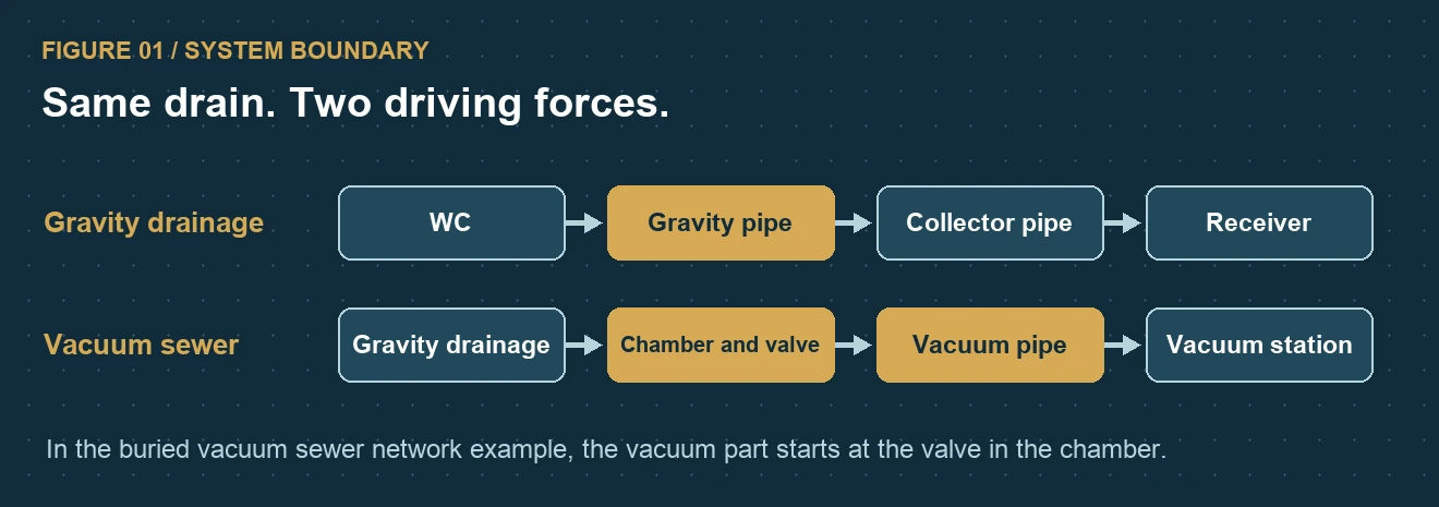
Gravity drainage relies on a difference in level. In the vacuum section, an interface opens to admit air and wastewater, which move under a pressure difference. Beyond the pump or station, the wastewater follows the designed discharge route.
Three ways to start drawing
Vacuum WC → vacuum line → local pump → receiving point. Fixture draining by gravity → interface valve → vacuum line → station. Building with gravity drainage → collection chamber → vacuum valve → buried vacuum sewer network → station.
Air and liquid interact
Flush volume is part of the transport process. Pipe profile, length, lifts, air volume and loading also affect performance. Check the approved operating conditions before making a change.
 View larger image ↗
Figure 1. Locate the transition from gravity drainage to vacuum in the chamber example.
Exercise
Draw one of the chains. Circle the vacuum source and underline the interface. Mark which sections belong to the building and the buried vacuum sewer network.
Background: [1], [2], [4], [6].
02 / SYSTEM SELECTION
Why choose vacuum drainage?
Vacuum can solve different problems in a holiday home, a refurbishment or a residential area. Start with what the project needs to achieve.
Water use and separate collection
Low flush-water use can help where water supply or tank capacity is limited. Collecting toilet wastewater separately allows it to receive separate treatment. The benefit also depends on what happens to the water and waste after collection.
Pipe routes and installation
In a refurbishment, vacuum pipework may allow routes around obstacles. In buried networks, the designed profile can reduce trench depth along some sections. Ground levels and crossings determine what is feasible.
What else needs to be considered?
The system needs power, monitoring and servicing. Assess noise, spare parts, access, alarms, the consequences of a shutdown and responsibility after handover. Compare water use, energy, excavation, tank emptying and servicing over the same period.
Ask before system selection
What specific problem must the system solve? Which assumptions about loading and operation must hold for the expected benefit to be achieved?
Background: [1], [6], [8].
03 / SWEDEN
From holiday homes to urban districts
Swedish applications include on-site wastewater systems, building installations and shared networks. Product availability does not show how widely a system has been installed.
On-site wastewater systems
Wostman, FANN and Jets illustrate different solutions for small properties. One layout collects toilet wastewater in a sealed tank and handles greywater separately. In Swedish documents, BDT means water from bathing, dishwashing and laundry. Check each flow against the project documents and municipal decision.
Larger buildings and shared networks
Evac’s central units and interfaces show how fixtures can connect to a building network. In Roediger’s sewer example, the interface valve in the collection chamber joins gravity drainage to the vacuum sewer. Design and testing must follow the selected system.
Oceanhamnen in Helsingborg
NSVA describes three separate streams: toilet wastewater, greywater and food waste. Identify each connection, check compatibility and locate the connection point. The project documents define the system boundaries.
Use the examples with care
Use the examples to recognise system principles. Check the model, document revision, local support and spare parts before each job. This handbook does not provide verified figures for market share in Sweden.
Background: [2]–[8].
04 / WOSTMAN AND FANN
When the tank is part of the vacuum system
Two products can be similar to each other for the user. Behind the WC, they may require different tanks, controls and installation materials.
Wostman EcoVac
Distinguish BASE from EXTEND. In the BASE example, the tank must withstand the specified vacuum. BOSS:2 is a separate collection solution with its own documentation. Use the instructions for the correct variant, including winter operation and service access.
FANN Green
FANN specifies the ST3000R for this vacuum system. The control unit, vacuum unit, tank and level functions must match the supplied package. Where both are described, distinguish a measured level signal from a calculated tank-emptying warning.
What is shared, what differs
In both cases, follow the wastewater to its destination. Identify an existing tank before considering reuse. A tank from another package, even with the same capacity, may have different connections or a different vacuum rating.
Your task
You find a buried tank with unreadable markings. List three details you need. Then check your answer against these points: model, documented vacuum rating and connections required by the system instructions.
Background: [2], [3].
05 / JETS AND EVAC
In-line pumps and upstream collection tanks
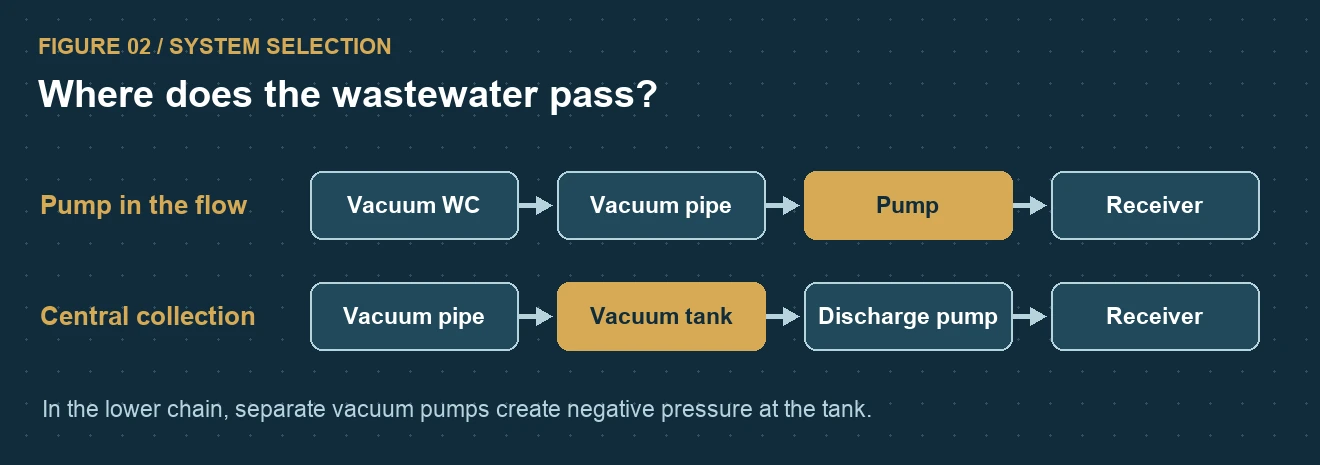
Both examples use vacuum to transport wastewater. The difference becomes clear when you trace whether the wastewater passes through the pump.
Jets VOD and Vacuumarator
In the VOD example, the pump creates vacuum on demand and moves wastewater onwards. Mark the vacuum inlet and the discharge side. Relocating the pump can affect both pipe routes, frost protection, access and the discharge point. Use the correct piping guide and project-specific documents.
Evac N°30 HQE
Here, wastewater collects in the vacuum tank before the vacuum pumps. Evac also describes interface valves that connect suitable gravity-drained fixtures to a building’s vacuum network. Check the specified flow, fixture and interface.
Evac VacuConvert
VacuConvert is a separate refurbishment example. Check WC compatibility, installation, service access and operation in the product documents. Use the installation and service manual for the actual equipment.
Compare
When moving a pump in the Jets example, check the inlet and discharge pipe routes. For a new sink in the Evac example, start by checking the connection principle and approved interface.
 View larger image ↗
Figure 2. Follow the wastewater. Which pump does it pass in each example?
Background: [4], [5].
06 / ROEDIGER AND VACUUM SEWERS
From collection chamber to vacuum station
In Roediger's film, the wastewater flows by gravity from the building to a collection chamber. The pneumatic vacuum valve opens so that waste water and air enter the buried vacuum sewer network.
Pause the film at three points
0:23–1:05: follow the gravity drain and identify the interface valve. 1:08–1:30: follow the buried pipe profile and locate the lifts. 2:17–2:49: distinguish vacuum pumps from wastewater discharge pumps.
Pipe profile and leak testing
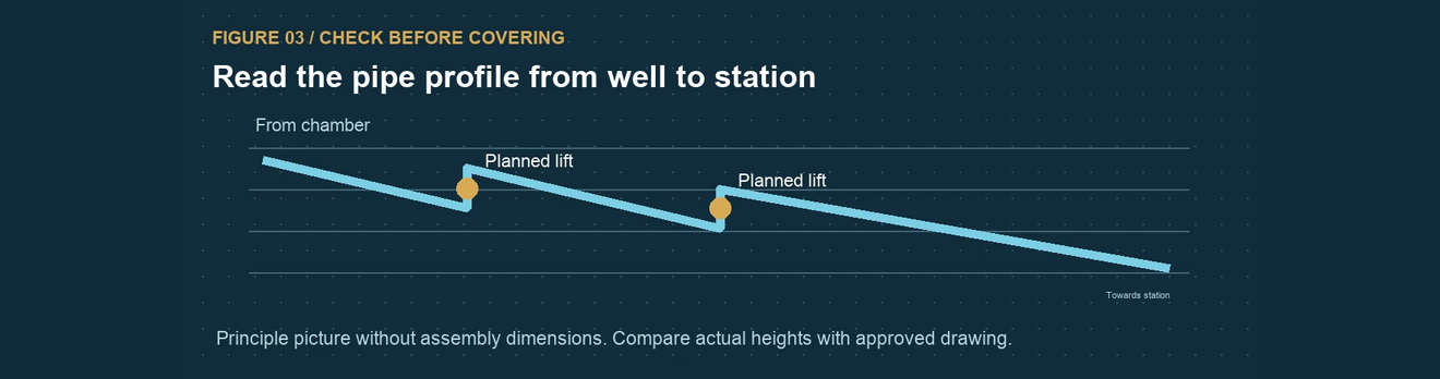
Check the designed profile, levels, lifts and crossings. Record the as-built position before backfilling. The film’s burial depth is an example, not an installation rule. Follow the project documents for installation and leak testing.
Compare with a vacuum WC network
In the film, the vacuum section begins at the chamber valve. In a building with vacuum WCs, it may begin at the WC interface. This distinction determines the test boundaries and responsibilities.
Decision before concealment
An existing pipe obstructs the proposed route. Measure and record the conflict, then ask the designer to assess a revised profile. Follow the decision and record the required checks before backfilling.
 View larger image ↗
Schematic. Follow the pipe profile and compare actual levels with the approved drawing.
Background: [6], [7].
07 / EUROPE
From water savings to resource recovery
European projects combine vacuum collection with different treatment processes. Results describe the installations and conditions in which they were measured.
Germany · Jenfelder Au in Hamburg
In Hamburg Wasser’s concept, toilet wastewater travels under vacuum to a local biogas plant. Greywater is collected separately. Correct pipe identification and connections are essential to keeping the streams separate.
Sweden · Oceanhamnen and RecoLab
Three streams are collected separately and treated at a local development facility. Consider what would happen if a fixture were connected to the wrong pipe. Follow the facility’s design and commissioning documents.
Belgium, the Netherlands and Spain
Run4Life documents demonstration sites in Ghent, Sneek, Vigo and Helsingborg. They combined technologies in different ways to study resource recovery from wastewater. Check each site’s purpose and system boundaries before comparing results.
What do these examples demonstrate?
They show applications in several countries and at different scales. They are not comprehensive European market statistics. Compare documented projects and state exactly what each source describes.
Background: [7], [9], [10].
08 / INSTALLATION
From drawings to installation checks
Inspection records must remain understandable after the pipework is concealed. During work planning, agree who checks each item and when work must stop.
Before installation
Check the model, part number, drawing revision, material and jointing method. Identify pipe routes, lifts, branches, service access and outlets. Assess frost risk, nearby installations and anything that will become inaccessible after enclosure.
Before concealment
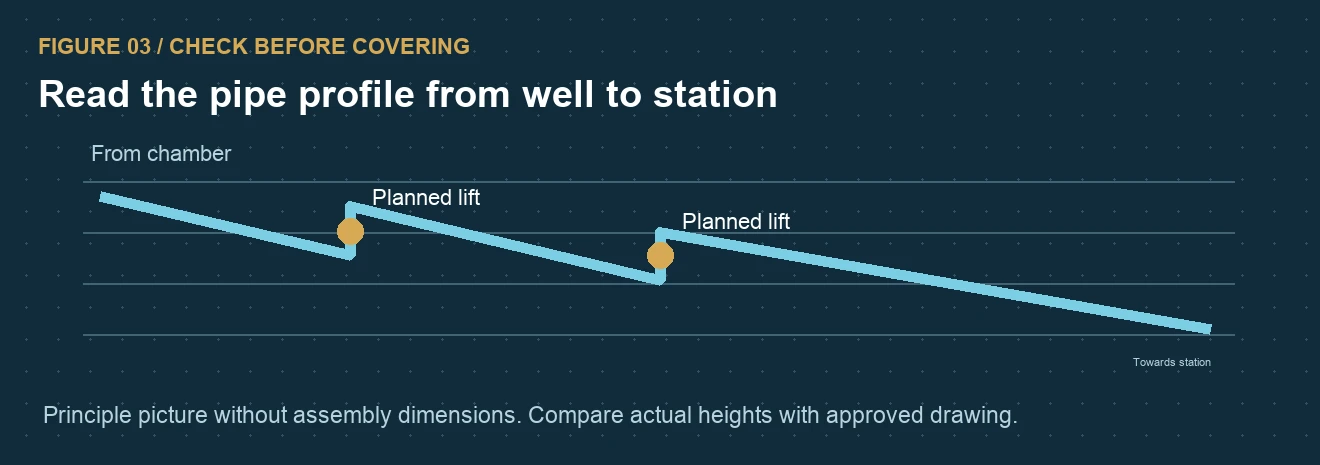
Compare the as-built measurements with the approved profile. Check joints, bedding and affected components against the inspection plan. Save dated, location-labelled photos. Record deviations and confirm decisions and required tests before concealment.
When a drawing is missing
Document what is missing and who is responsible for producing the documentation. A product sheet can identify a valve. The installation instructions for the correct model are needed to check the installation.
Record a deviation
Record the location, observation, drawing revision, missing information, work on hold and the person responsible for the next decision.
 View larger image ↗
Figure 3. Mark the planned lifts. Record the as-built position before covering the pipework.
Background: [2]–[6].
09 / WORKING ENVIRONMENT
Work safely before opening the system
A stationary pump can start automatically. Vacuum, discharge pressure, electrical or pneumatic energy and incoming flows can affect the work area.
Identify and secure
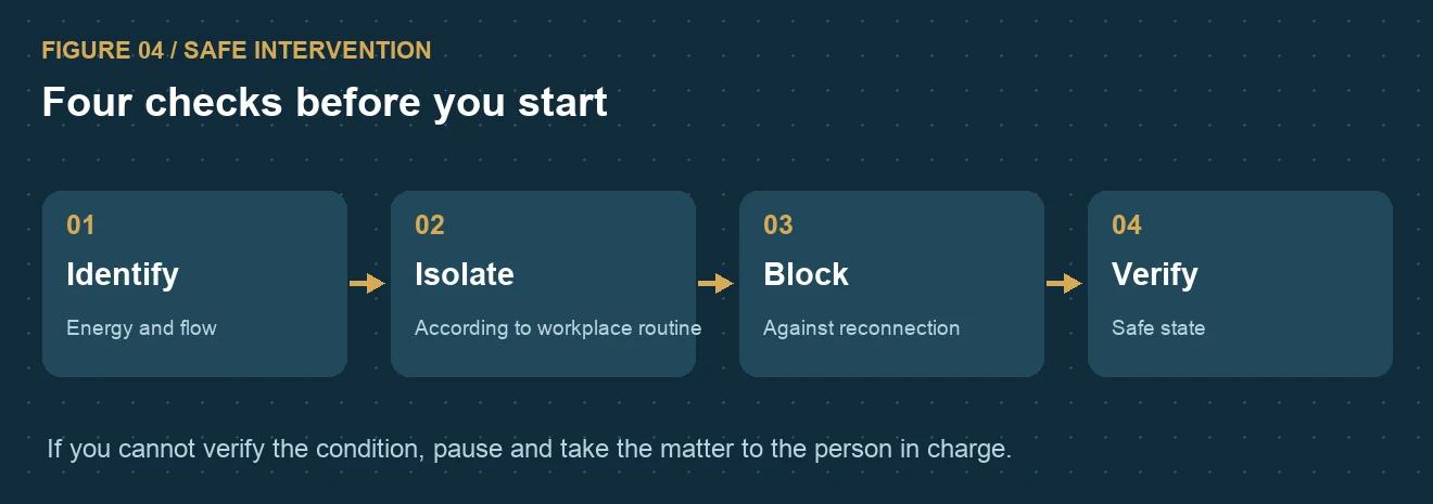
Agree the work boundary with the operator. Identify all relevant energy sources and flows. Follow the site procedure for isolation, preventing restart and managing residual energy. Verify a safe state using the specified method before opening the system.
 View larger image ↗
Figure 4. Four steps in work preparation. The facility's routine governs the practical work.
Chambers, tanks, pump pits and trenches
Assess hazardous atmospheres, incoming flows, falls, trench collapse, traffic, splashes and infection. The employer must plan safe access, monitoring and rescue as required. In an accident, raise the alarm and follow the rescue plan. Never enter to attempt an unplanned rescue.
Return to operation
Check that people and tools are clear, guards are refitted and the operator has authorised restart. Document the change and complete the required functional checks.
When to stop work
If the safe state, isolation method or access arrangements are unconfirmed, stop and consult the person in charge. A stop button or AUTO indication does not prove the equipment is safe to work on.
Background: [11], [12].
10 / TESTING AND COMMISSIONING
Record test results others can verify
An installation may pass a leak test yet fail in operation. Pre-concealment inspection, leak testing and functional testing answer different questions.
1 · Define and prepare
Before testing, record section, drawing revision, method, instrument, conditions, acceptance criterion and responsible person. Resolve deviations that could affect the test.
2 · Test and document
Record readings, times, operating conditions and deviations. Follow the approved method and the inspection plan’s requirements for retesting. The test plan defines which connections, loads and alarms must be functionally checked.
3 · Hand over
Gather as-built drawings, the equipment list, document revisions, test records, operating values, service points and contact details. Show the operator the interfaces and isolation points, and explain how to report faults.
Review a test record
An entry that says only “OK” does not show what was tested or which requirement applied. Record the test section, method, results and responsibility in accordance with the project procedure.
Background: [4]–[6].
11 / TROUBLESHOOTING
Start by finding the extent of the fault
These examples help you choose a safe first check. Follow the product instructions and site procedures before any intervention.
A WC works poorly
Check if other devices are working. Separate flushing water, valve operation and vacuum transport. Compare with the product's troubleshooting documentation.
A valve does not close
Identify valve and control. Check observations and operating trend. Roediger's troubleshooting information lists water in control hoses as one possible cause. Follow the isolation procedure and verify a safe state before dismantling.
Several connections fail after groundworks
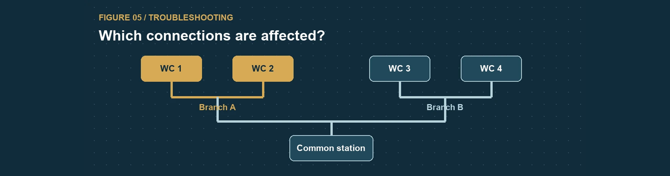
Locate the shared branch and recent work. Compare logs, as-built levels and previous tests.
The station runs longer than usual
Compare alarms, loading and vacuum recovery. Investigate possible causes such as air leakage, a valve remaining open or a station fault.
Problems during rain or snowmelt
Compare operating data with weather and site conditions. Follow the operating plan to investigate whether water enters through an incorrect connection or infiltration.
Works for one flush but fails under load
Record the time, simultaneous use and affected section. Compare with the design operating conditions. With the operator, check vacuum recovery and the air and liquid flows.
 View larger image ↗
Schematic. Two WCs on the same branch are affected. Start by locating the fault.
Background: [2], [4], [5], [6].
12 / SELF-STUDY
Practise before the final assessment
Write short answers before reading the suggested answers. Use four points: what you observed, what information is missing, the next safe step and who is responsible.
A · Same fault, two installations
A WC works poorly in a house with a local pump. The same symptoms occur in a house with shared vacuum. What do you investigate first in each case?
B · Crossing before backfilling
The work team wants to put in an extra lift to get past a line. What needs to be measured and who needs to assess the change?
C · The pump is stationary in AUTO
A service operation requires opening a valve housing. What must be verified before the procedure?
D · New basin on a vacuum system
The drawing shows the basin’s gravity waste pipe leading towards the vacuum network. What information do you need to assess the connection?
Suggested answers
A. Local pump: identify the pump, controls and receiving point. Shared network: establish the extent of the fault and coordinate with the operator. B. Measure and record the conflict; await the designer’s decision before covering. C. Verify isolation, restart prevention and safe conditions for all energy sources and flows. D. Check the specified interface, flow and service access.
Continue with the web course job scenario and then complete the final assessment.
13 / SOURCES
Consult the original sources
This handbook explains key principles. The cover photograph shows general plumbing work. The schematics explain functions, not specific product models. Use current product instructions and approved project documents for installation, testing and servicing.
[1] HaV · Vacuum toilets in existing houses
[2] Wostman · EcoVac, BOSS:2, troubleshooting and winter instructions
[3] FANN · Green Toilet system, tank and control
[4] Jets · VOD manuals, pipe guide and frost protection
[5] Evac · N°30 HQE
[6] Roediger · Vacuum sewer systems
[7] NSVA · Tre rör ut, Oceanhamnen
[8] Jets Sweden · areas of application
[9] Hamburg Wasser · HAMBURG WATER Cycle
[10] Run4Life · European demonstrations
[11] Swedish Work Environment Authority · safe use of work equipment
[12] The Swedish Work Environment Authority · dangerous atmosphere in closed spaces
Additional sources for [5]: interface valves and VacuConvert, installation and service manual.
Additional sources for [6]: Roediger Construction Manual Rev. 6, chapters 1, 2, 4, 6 and 7, the system video and troubleshooting guidance.
14 / FURTHER PRACTICE
Read the operating data
Use the operating log to decide where to check next. Treat the events below as a fictional site scenario.
08.10 · Before work
The station’s vacuum recovers after loading. Both branches work.
09.00 · After work
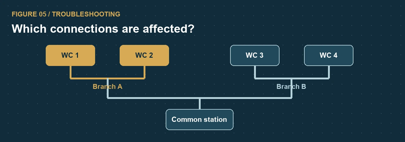
Two WCs on branch A lose function. Branch B works. The station's vacuum level recovers more slowly than before.
 View larger image ↗
Figure 5. The highlighted WCs share branch A. Which part of the system would you check first?
Your task
Write down what you know. Differentiate it from what you suspect. What information should you obtain from the operator before proposing an inspection?
Suggested answers
The fault affects branch A after the work. Check the work log, alarms, current loading and affected connections. Do not adjust settings or open equipment without the required information and a safe working method.
15 / ON-SITE CHECKLIST
Installer’s checklist
Use this checklist in the exercise and add the project’s own inspection points. Record the location, section, drawing revision, date and person responsible.
Before installation
Correct model and instructions. System boundary and receiving point. Pipe profile, planned lifts, service access and responsibilities at interfaces.
Before concealment
Measurements and photos with location. Joints and pipe bedding according to control plan. Deviations assessed. Prescribed tests documented.
Before intervention
Work boundary agreed with the operator. Energy sources and flows identified. Equipment isolated and secured against restart. Safe state verified.
Before handover
Traceable test results, as-built drawings, correct manual revision, service points, outstanding deviations and contact details.
If something is missing
Write what is missing and what work needs to be paused. Specify who makes the next decision.
16 / GLOSSARY
Terminology on the job
Use these terms when describing an installation or reporting a fault.
Interface
Where two parts of a system meet. In the buried network example, gravity drainage meets the vacuum section at the collection chamber valve.
Test boundary
The start and end of the section under test. Mark the boundary in the test record so others can see what the test covered.
Isolation
Disconnecting equipment from energy sources under the site’s safe working procedure. Also check residual energy and the risk of automatic restart.
Pipe profile
A drawing showing how the height of the line changes along the route. Use it to compare planned heights and lifts with what is being built.
Greywater (BDT in Swedish)
Water from bathing, dishwashing and laundry. Check its route in the installation.
Try it yourself
Point out interface and test boundary on a sketch. Explain to yourself how you would report them to the operations manager.
17 / BUILDING ON YOUR EXPERIENCE
From gravity to vacuum drainage
Experience with conventional drainage gives you a sound basis for reading pipe routes and assessing joints, access and workmanship. Here is what changes.
Gravity drainage uses a height difference. Vacuum drainage uses a pressure difference.
A gravity drain follows the designed fall. In a vacuum system, a valve admits air and wastewater to the vacuum pipe. The profile may include designed lifts. Mark gravity, vacuum and any pumped discharge sections separately.
Check both tightness and operation.
On the vacuum side, leaking air can affect transport and the operation of the pump. Check for correct joints and test method. Find out where the vacuum is created and what happens if the pump, valve or control stops.
Less flushing water is a possible gain.
A vacuum WC can use less flush water. The European Commission’s RecoLab example reports 1–2 litres per flush, against 6–8 litres for the comparison. A vacuum sewer serving conventional WCs does not automatically save flush water. In Hamburg, toilet wastewater is collected separately for local biogas treatment.
Assess gas risks and service life
Gas formation depends on wastewater and operating conditions. Materials, joints, loading and installation affect service life. These sources do not establish a general increase in service life. Assess hydrogen sulphide and other hazards in chambers, tanks and stations.
Try the calculation
With 20 flushes a day, what is the difference between 6 and 1.5 litres per flush? Answer: 90 litres a day in this example.
Hamburg Wasser · negative pressure technology · EU · RecoLab · US EPA · hydrogen sulfide
18 / AVOIDING COSTLY REWORK
Check before concealing pipework
Use these checks when moving from gravity to vacuum drainage. Note what will be concealed, what must be checked and who decides whether work can proceed.
Profile and joints
Vacuum pipework must follow the designed profile, including planned lifts. Measure a proposed change before the designer assesses it. Air may leak in without visible wastewater leakage. Use the specified leak-test method.
Pipe, valve and pump
Check pipe material, size, joints, flow direction and control connections. Mark the vacuum section and any pumped discharge. Check both sides when a pump is relocated.
Flows and service access
Label toilet wastewater, greywater and other streams, and trace each to its destination. Ensure service points remain accessible after enclosure. Check frost protection and level functions where specified.
Tightness and function
Document the leak test for the defined section. Then test the operating cases specified in the test plan. Consult current product instructions before changing flush volume or controls.
Test your decision
An extra lift has been built and a WC passes a flush test. Concealment must wait until the profile has been assessed and prescribed checks and tests documented.
Background: [2]–[7]. NSVA's documented choice for Oceanhamnen.
19 / BACKFLOW AND CONTAMINATION
Air ingress, wastewater backflow and backflow into drinking water
Identify which pipe and which flow you are talking about. Three different problems can otherwise be given the same name in the workplace.
1 · Air into the vacuum side
The valve admits air as part of the transport when it opens according to the function of the system. Air leaking in unintentionally at a joint or component can affect the vacuum level and operation.
2 · Wastewater backflow
Check the discharge route, levels and specified backflow protection. Verify the component and orientation required by the project. This check is separate from vacuum-side leak testing.
3 · Drinking-water contamination
Protect the drinking-water connection against backflow as required by the applicable rules and approved installation documents. Identify the required protection before connecting or replacing equipment.
Draw and compare
Mark the tap water inlet, vacuum line and outlet on a sketch. Write down what can go wrong in each part and what documentation you need before correcting the error.
Safe Water Installation 2026:1, section 5.3 · Manufacturer documentation [2]–[6].
20 / DRAWING EXERCISE
Read the chamber drawing from both sides
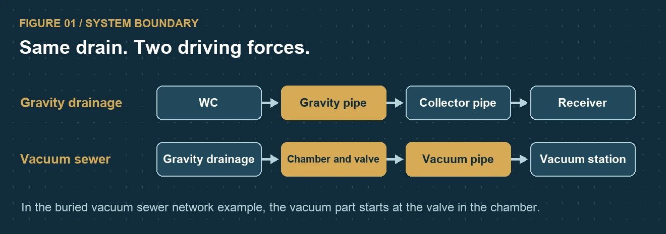
First find the pipe from the building. Follow it to the collection chamber. Then start at the station and follow the vacuum line backwards until you reach the interface valve.
 View larger image ↗
Drawing aid. In the lower example, wastewater flows by gravity to the chamber. The vacuum pipe runs from the valve towards the station.
On the gravity side
Locate the property’s drain and inspection point. Check the ventilation route on the approved drawing. Select inspection points from the project documents.
On the vacuum side
Point out the valve, which section is to be tested for tightness and the route to the station. When the valve opens, waste water and air enter the network.
Do it yourself
Sketch the property’s drain, inspection point and vent from the approved drawing. Mark the system boundary. Note who you must coordinate with and which section will be tested. Identify who must provide any missing information.
The web course's Swedish drawing exercise · Extra knowledge and Swedish sources.
Practical assessment · Trace a loss of vacuum
On the training rig, vacuum recovers more slowly after a discharge than it did during the baseline run. Air can still be heard entering after the interface valve should have closed. On the drawing, mark the gravity inlet, the valve, the gauge point and the line to the station. Show how air and foul water move when the valve opens.
Show how you would make the rig safe before opening anything. To pass, identify the measurement point, separate what you observed from what you suspect, and record the tightness test and functional check separately.
Assessor notes
Compare the reading with the baseline for this rig. A valve failing to seal and a leaking joint are both possible causes of vacuum loss. Explain how the rig procedure lets you tell them apart. If the line passes its tightness test but fails to clear during operation, check the installed pipe profile against the drawing and refer to the valve instructions for functional checks.