


Example: vacuum WC → vacuum line → station or specified interface. Follow the current product manual for connection, setup and service access.
Step 1 / Read before starting the exercises
Start with the course handbook
Read the handbook before starting the exercises. Its diagrams explain system boundaries, pipe profiles, pump arrangements and safe troubleshooting. The English handbook has 23 pages. Read on screen or save the PDF to read later.
Inside the handbook
- Chapters 1–3 · Understanding the basics
- Follow air and wastewater. See why vacuum is chosen and where the technology is used in Sweden.
- Chapters 4–7 · Get to know the systems
- Compare Wostman, FANN, Jets, Evac and Roediger. See how the solutions are used from single-family houses to neighbourhoods in Sweden and Europe.
- Chapters 8–11 · Installation, testing and troubleshooting
- What you check before installation and covering, how you work safely and where to start looking when something goes wrong.
- Chapters 12–20 · Practice, look up and bring to work
- Work through four job scenarios and compare your answers with the examples. There are also sources, an exercise case about the operating log and a work checklist.
New to vacuum drainage? Start with the comparison with gravity drainage, then read Chapter 1. Draw the path from the WC to the receiving point as you read. You will use the same way of thinking in the exercises.
I have read · go to the lessons →Study at your own paceUnderstandPrepareAssembleTestTroubleshootHand over
01 / 15 minutes
Follow the wastewater and the air
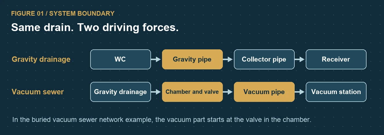
Waste water is collected in the buried vacuum sewer network before the vacuum valve. When the valve opens, wastewater and air are introduced into the vacuum line. The vacuum station creates the pressure difference that drives the transport.
In a building, for example, a vacuum toilet or other approved connection device can be the interface to the vacuum line. Interface is the point where two parts of the system meet. First establish which system the drawing shows and which product instructions apply at the connection.
"Gravity drainage has worked for years. Why use vacuum here?"
Gravity drainage is a good choice when the pipe path, the heights and the operation work. The question is which problem this particular job needs to solve. In a building, a difficult pipe route can be decisive. In a single-family house, the availability of water and the collection of WC wastewater can be more important. In a district, it may be important to be able to treat the WC flow separately.
Three objections you may hear at work
"There will be more parts that can break." Yes, valves, controls and vacuum pumps need servicing. Ask for information about who responds to alarms, what happens if the system stops and whether the components can be reached. Weigh that against what the simpler pipe route or the lower flush water amount provides in that particular project.
"I want to see that it works when the house is used." Ask for a test plan that corresponds to the operating cases the plant must handle. A test flush shows how a connection works at that time. Operation and handover require documented controls according to the project's plan.
"Can we lay the pipe as we usually do?" Build on your experience of reading drawings and inspecting joints. For vacuum drainage, also check system boundaries, airtightness, the pipe profile and access for servicing. Agree any changes before the work is concealed.
Exercise · would you choose vacuum here?
Job A. A normal pipe route with a good fall already exists and the project has no special requirements for flushing water or separate flows.
Job B. In the case of a rebuild, the gravity drainage path is difficult to achieve. The customer also wants to collect the WC wastewater separately and can arrange service access.
Choose the job where you would investigate vacuum drainage further. Explain what you need to confirm before recommending the solution.
Compare with an example answer
In job A there is a clear route for a gravity drain. In job B there are two concrete reasons to investigate vacuum. Confirm pipe path, load, operational responsibility, service and cost over time before recommending a solution.
Used to gravity drainage? Start here
You can already follow a pipe on the drawing, get tight joints and make sure the installation is serviceable. In a vacuum system, you also need to be able to point out where gravity drainage ends, which valve opens into the vacuum line and what creates the vacuum.
| At work | Gravity drainage | Vacuum |
|---|---|---|
| What drives the flow? | Height difference. The wastewater flows down the pipe. | Pressure difference. When the valve opens, wastewater and air are introduced into the vacuum line. |
| How do you lay the pipe? | Follow the specified gradient and pipe size. | Follow the designed profile, including any specified lifts. Check the heights where the pipe actually ends up. |
| What must the joints withstand? | Wastewater and the tightness requirements that apply to the installation. | Joints must also be airtight where the pipe is under vacuum. Air that leaks in can affect the transport and the operation of the pump. |
| What could stop the flow? | A pure gravity drainage section does not need a vacuum pump for the water to flow. There may be other pumping further away. | The system depends on the valve, pump and controls working together. A fault can affect a WC, a branch or the entire network. |
| What happens to the water? | Flush water helps move the contents out of the WC; the wastewater then flows down the sloping pipe. | A vacuum WC can use less flushing water. In buried vacuum sewer networks with regular WCs, the water saving does not come automatically from the ground pipe itself. |
Why choose vacuum? A project may want to reduce flushing water, collect WC wastewater separately or install pipework where gravity drainage is difficult. In Oceanhamnen, the EU Commission reports 1–2 litres per flush for vacuum WCs in the project, compared to 6–8 litres for the conventional WCs used as a comparison. Hamburg uses negative pressure to feed a separate WC flow to a local biogas plant. These are examples of why European projects have chosen the technology.
Two projects · what should the installer understand?
Oceanhamnen, Helsingborg
Three separate streams reach RecoLab: toilet wastewater, greywater and food waste. The European Commission reports 1–2 litres per flush for the project’s vacuum WCs, compared with 6–8 litres in its comparison.
For the installer. Trace each stream on the drawing. Check connection points and approved products. Flush volume describes WC flushing, not the whole district’s water or carbon savings.
Jenfelder Au, Hamburg
A vacuum system carries toilet wastewater separately to a local biogas plant. Hamburg Wasser describes reduced flushing water and separated flows as parts of the district’s resource recovery system.
For the installer. Distinguish transport from treatment. Check the pipe profile, valves and service access against the project documents. Assess environmental benefits across the whole system, including energy use and operation.
Sources and system descriptions: EU · RecoLab · Hamburg Wasser · HAMBURG WATER Cycle
Water use · compare two toilets
Exercise: compare 6 litres with 1.5 litres per flush at 20 flushes per day. How much difference does it make?
Check your answer
The difference is 4.5 litres per flush, i.e. 90 litres per day in the calculation example. For a real project, you need actual flush volumes, usage and data on the rest of the system.
Gas, corrosion and service life
How long the line lasts depends, among other things, on material, joints, load, installation and operating environment. Gas formation also depends on how long the wastewater stands, temperature and biological conditions. Vacuum can provide different transport and air conditions, but service life must be assessed for the particular installation. Hydrogen sulfide and other risks still need to be assessed at chambers, tanks and stations.
Hamburg Wasser · manual on negative pressure technology (PDF) · European Commission · RecoLab · US EPA · hydrogen sulfide and corrosion
Nine differences that can lead to costly rework
You already know the craft. These are the control points where a habit from gravity drainage can lead to error. For each point, ask yourself what is being hidden and what you need to check before building further.
01 · The pipe profile looks like it will fit
For gravity drainage, check the designed gradient. In a vacuum system, you need to read the entire profile, including planned lifts and low points. A move around an obstacle can change the transport. Measure the intersection and get an approved solution before covering.
02 · The joint is dry but air leaks in
On the vacuum side, air can enter without visible wastewater exiting. Follow the approved jointing method and check tightness according to the project's test plan. A dry joint is an observation, not a test result.
03 · Same pipe diameter as last job
Check dimension, material, joint type and the suitability of the components for the operating case. A part may fit physically but have the wrong properties or be intended for another side of the system.
04 · The valve and the pump get the wrong connection
Identify inlet, outlet, flow direction and any control connection in the instructions. Distinguish between vacuum line before pump or station and any pumped outlet. Check them individually when the pipe path is changed.
05 · WC, greywater and stormwater are mixed together
A drawing can show several separate flows. Label both ends, follow the pipe to the receiving point and verify each connection before concealing the pipes. A sink draining by gravity may need a designed interface to vacuum.
06 · The flush volume is changed to save more water
Air, liquid, pipe profile and load work together. Check the product instructions and transport conditions before making changes. A single functioning flush test does not show how the system can cope with the designed load.
07 · Access for servicing is blocked
Check that valve, control, shut-off and other prescribed service points can be reached after the pipework is enclosed. Also check any specified frost protection and level monitoring.
08 · Leak test and function test are mixed together
The tightness test covers a defined section using a specified method. The function test shows how the plant functions in specified operating cases. Record what was tested, what passed and what still needs attention.
09 · A system fault is treated as an ordinary pipe blockage
First check whether a WC, a branch or the entire network is affected. Pump, valve, controls and air leakage can cause similar symptoms. Coordinate with the person responsible for operation and verify that the equipment is safe before working on it.
Three distinct risks to check
- Unintended air leakage into the vacuum pipe. An interface valve admits air as part of its operating cycle. Air entering through a leaking joint is unintended and needs to be investigated.
- Wastewater backing up into the building. Check the discharge side, connection levels and prescribed protection against backflow in the documents for the particular system.
- Backflow into the drinking-water supply. A separate risk of contaminated water being sucked or pushed into the drinking-water installation. The protection is selected according to applicable requirements and approved product and project documentation. A valve on the wastewater side fulfils another function.
NSVA · design choice in Oceanhamnen · NSVA · commissioning · Säker Vatteninstallation (Sweden) · protection against backflow, section 5.3
Two installations you may encounter
Example: gravity drain → collection chamber → vacuum valve → buried vacuum sewer → station. Read the profile drawing and check who is responsible on each side of the chamber.
Watch the valve work, step by step
Choose a step and follow what happens in the chamber. The exercise shows the principle of a buried vacuum sewer network with a collection chamber.
The valve is closed. The wastewater flows by gravity and is collected in the chamber. The vacuum is on the network side of the valve.
Check question · where does the vacuum part begin?
In this example, it starts at the interface valve. The piping from the building to the chamber runs by gravity. A vacuum WC inside the building may have a different system boundary.
Video exercise. At 0:23, identify the gravity drain. At 1:08, follow the buried pipe profile. At 2:17, distinguish the vacuum pumps from the discharge pumps. Pause and mark each system boundary on your sketch.
Exercise. Draw the route from collection to station. Mark where wastewater enters, where air enters and where negative pressure is created.
Check your answer
The collection is located before the valve, wastewater and air pass through the valve and the vacuum pumps are located at the station. Then explain which interface would apply in the building on your own project.
The manual, sections 1.1 and 2.1. See also the system video.
Optional further study / 15 minutes
Follow gravity flow to the collection chamber
This is a Swedish drawing exercise. You start on the side of the property and follow the water up to the valve. Then use the drawing to find what you need to check on a real job.
1 · On the property side
Follow the gravity drainage line up to the chamber. Locate where you can inspect the line and where the vent is drawn. Write down what is missing before building further.
2 · At the valve
The chamber collects the wastewater. When the valve opens, wastewater and air enter the vacuum line. Point out which part is under vacuum when the valve is closed.
3 · Towards the station
Follow the vacuum line from the valve. Mark the section to be tested and who you are to coordinate with during the transition between property and network.
Check question · what do you do if the inspection point is missing?
Pause the affected connection and ask the person in charge to confirm the inspection point, venting, limit of responsibility and test section. Use the drawing for the Swedish project to determine placement and execution.
Go to Extra knowledge · Open the drawing exercise in the course handbook
02 / 20 minutes
Go through the documents before installation
- Agree on current drawing and revision, scope and responsibility at the transition between building and buried vacuum sewer network.
- Identify which flows to connect. Check how toilet wastewater and any wastewater from baths, washing up and laundry are handled. Keep rainwater outside the vacuum sewer as described in the manual.
- Match pipe, joint method, components, accessibility and test requirements against the documents for the current installation.
The flush volume is part of the system. Roediger's feedback emphasizes that air and liquid, transport distance, fall, lift and wastewater type need to be assessed together. Find the specified setting in the current product manual and project documents.
Simulated conversation before installation
Next question · can we lower the flush volume?
The supervisor wants to save water. State what you need to know before you answer.
Compare with the tutor's answer
View the correct product instructions and check which transport route and load the setting should work with. Refer any proposed change to the designer or supplier if the project documents do not cover it.
The manual, sections 1.1, 1.4 and 2.2. Manufacturer's technical feedback.
03 / 25 minutes
Check before covering the pipe
- Compare the location, heights and profile of the line against the approved drawing. Check branches and lifts where changes easily occur.
- Check pipe bedding, joints and access to inspection points according to the project's work plan.
- Record the installation as built. Save measurements, photos and test results with location, date and drawing revision.
- Record deviations and keep the affected section open until the change is assessed and the checkpoints are completed.
Installation exercise. Another pipe blocks the projected path. The installation team proposes an extra lift and wants to backfill immediately. What information do you need before the work can proceed?
Check your answer
Measure the conflict and elevations, photograph and mark the affected section on the drawing. Let the responsible designer assess the change. Use the approved documents for installation, inspection and testing before concealing the pipework.
Practice reading a pipe profile
Checklist to bring to the work preparation
- Current drawing and revision, the pipe section and the person responsible for inspection.
- Measured heights, joints, pipe bedding and access where the project requires control.
- Recorded departures from the design, agreed actions and any required retesting.
- Test record and basis for decisions before concealment.
The manual, sections 2.1, 2.3 and 2.4.
04 / 20 minutes
Test, establish the boundaries and document
The test boundary marks the start and end of the section being tested. Decide before testing which part is tested, who is responsible, which criteria apply and where the outcome is documented. Follow the project's test instructions for measurement procedure and limit values.
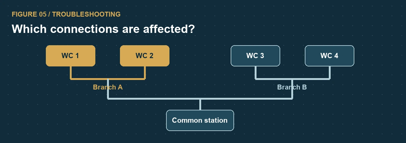
When a fault occurs, first establish which parts are affected. A connection, a branch or several branches provide different starting points. Read alarms and document time, affected parts and recent work. Follow the operating and safety procedures before intervention or shutdown.
Troubleshooting case. Three connections on the same branch lose function after installation work. Other branches work. What do you investigate first?
Check your answer
Confirm which connections are affected and when the error started. Identify the common branch and check alarms and work log. Follow the directions to narrow down the error before blaming a specific component or changing settings.
Show the answer on the picture
Start with branch A and read the operating log. Confirm the scope before deciding that a particular valve is at fault. If both branches are affected, also investigate the common network and the station with the operator.
Example of a useful error report
"Three connections on branch B have lost function. Branch A is working. The error was discovered after assembly at B2. Scope, time and alarm picture documented. The next step is to investigate branch B using the operating instructions."
A good report separates observation from suspected cause and indicates who will take the next step.
The manual, sections 2.4.4, 6 and 7. Use the project's approved operating and testing instructions.
05 / 25 minutes
Make the installation safe before work starts
A pump that is standing still can start automatically. A stopped motor does not establish whether there is residual vacuum, pressure on the outlet side, pneumatic control or inflow. Go through the entire work area and coordinate the shutdown with the operations manager.
When to stop work. Stop the work if the team cannot verify how to isolate the equipment, prevent a restart and confirm a safe condition. A stop button or a screen display cannot replace checks at the equipment.
- Identify. Point out current equipment and which energy sources, levels and flows can affect the work.
- Secure. Isolation means separating the equipment from energy sources that could affect the work. Have designated personnel follow the plant's procedure for isolation, preventing reconnection and dealing with stored energy. Use the specified method to verify a safe condition before starting work.
- Protect the work area. Assess exposure to wastewater and splashes, hygiene, site barriers, traffic, lifting operations and excavations. Choose protection and work method based on the task.
- Restart under controlled conditions. Check that people and tools are out of the risk area, that protection has been reinstalled and that the operator has approved the return to operation.
Show examples of risks in the plant room
Check for power supply and automatic start, vacuum in tank or line, pressure on outlet side and wastewater that can be supplied. The operator and the project's documentation show where the boundaries and points of separation are.
Collection chambers, pump pits and tanks
Treat descent as a separate work task. Assess the atmosphere, the flow and the ability to get a person out quickly. If there is a risk of a dangerous atmosphere, the employer must apply the facility's planned working methods for, among other things, measurement, monitoring and rescue. In the event of an accident, raise the alarm and follow the rescue plan. Never enter to attempt an unplanned rescue.
Exercise · the pump is already stationary
You will open a valve housing. The pump is stationary and the operating panel shows AUTO. What information is missing?
Suggested answer. Who is responsible for isolation, where energy sources and inflows are isolated, how restarting is prevented and how safe conditions are verified during the work. If the work requires descent, a plan for confined-space entry is also needed.
Swedish Work Environment Authority · safe use of work equipment · Hazardous atmosphere in confined spaces · Excavation risks
06 / 30 minutes
From the reported fault to the first check
The fault symptoms below are typical cases from the manufacturer's documentation and teaching examples. Start with the scope, compare to previous metrics and keep multiple possible causes open.
A vacuum WC works poorly
Ask first. Is it a single unit? Did the problem come after assembly or service?
What to check. Check that the model and instructions are correct and which alarms or observations exist. Distinguish between bowl rinsing, valve operation and vacuum transport. Let the documentation guide troubleshooting and testing.
A vacuum valve in the buried vacuum sewer network does not close
Ask first. Is there persistent air suction or longer pump run times in the station? Which valve and control is there?
What to check. Among other things, the manufacturer mentions water in control hoses and problems with the control unit. Follow the correct model's service instructions and the plant's shutdown routine before disassembly or changing settings.
Several connections lose function after ground work
Ask first. Do they share a branch, junction or section where work was carried out?
What to check. Compare operating signals, shutdown modes and work log. Check the documented pipe profile and leak test for the affected section. Distinguish a profile or flow issue from a suspected leak.
The station runs more often and the vacuum slowly recovers
Ask first. Does it apply to the entire network? When did the trend change, and what changed in the system at the same time?
What to check. Examine the operating log and alarms together with the operations manager. Possible clues are increased air leakage, a valve that is open, a change in load or a station error. Agree how to narrow down the fault with the operator before replacing components.
The problem occurs during rain or snowmelt
Ask first. Does high load or level coincide with precipitation? Is there a suspicious connection point or chamber?
What to check. Compare historical alarms with weather and location. Check whether unintended inflow can reach the system, for example via connections or infiltration, according to the project's working methods.
The system works for a single flush but fails under load
Ask first. Does the fault occur when several toilets flush together, after a change to the flush setting, or on a particular section?
What to check. Document the load pattern and compare with the projected operating case. Check profile, air and liquid transport and station recovery together with responsible designer or supplier.
Roediger · troubleshooting questions · Construction Manual Rev. 6, sections 1.1, 2, 4 and 6.
07 / 25 minutes
Commission in documented stages
Documents approved, assembly checks carried out, deviations handled and responsibility for testing appointed.
Record the test section, method, instrument, test conditions, readings and acceptance criteria from the test instructions.
Verify the connections, alarms and operational cases included in the project test plan. Compare with reference values for the plant in question.
Provide the operations manager with as-built drawings, protocols, equipment list, remaining items and routine for reporting faults and safe shutdown.
Review a test record. The record only says “Tight — OK”. What would another person need to assess or repeat the test?
Show the assessment document
Identified route and drawing revision, test method, instrument, test conditions, requirements and measured result, responsible person and date as well as any deviations and retests. Signing and handing over follows the project's process.
Construction Manual Rev. 6, sections 2.4.4 and 7. Project-specific testing instructions govern execution and limit values.
08 / 35 minutes
Job scenarios · from building to buried vacuum sewer network
Scenario. A service building is connected to a buried vacuum sewer network. The installation team must deal with a changed pipe route, an incomplete test record and an operational failure after start-up. Make a decision at each step and compare your reasoning with the feedback.
Practice a deviation report
The writing exercise has an example for self-checking. The three decisions above determine when the job scenario is marked as complete.
Use the pipe profile in the course. An existing pipe obstructs the route between the last planned lift and the station. The levels have yet to be surveyed. Record what you observed, which information is missing and who needs to assess the next step.
Compare the example report with your own
"The existing line crosses the planned section between the last projected lift and the station. Heights and conflicting positions need to be measured and entered on the current profile drawing. The affected section is kept open. The responsible designer assesses any changed profile before installation and testing continue."
Complete your report if any point is missing. The example and the checklist are support for your own assessment.
09 / 45 minutes
Compare the systems behind the WC
Follow the wastewater and mark three points in each example: where the vacuum starts, where the negative pressure is created and where the wastewater goes. Then choose the right document for the job you are facing.
What the systems have in common
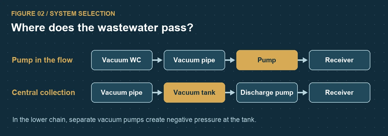
All the examples have an interface where wastewater is introduced into a vacuum part. The transport is driven by a pressure difference. Always draw the flow all the way to the receiving point and mark what is gravity drainage, vacuum and possibly pumped outlet. Follow the correct product instructions for connection and testing.
What changes for the installer
| Principle and example | Where is the vacuum? | What are you checking behind the WC? |
|---|---|---|
| Vacuum to closed tank Wostman EcoVac BASE, FANN Green | The vacuum unit works against the tank in the current system solution. | Identify the supplied system and tank. For FANN Green, the manufacturer specifies ST3000R. Read the documentation for the tank and its level monitoring. Draw a separate route for greywater where the project separates these flows. |
| Pump in the transport route Jets VOD | Vacuumarator creates a vacuum on the inlet side and carries the wastewater on to the outlet side. | Check the piping on both sides when moving the pump. Use the correct model guide and follow the wastewater on to the receiving point. |
| Central vacuum collection in building Evac N°30 HQE | A central unit maintains a vacuum in the building's network. The collection tank catches the wastewater before the vacuum pumps. | Distinguish vacuum WCs from gravity-drained fixtures connected through an interface valve. Check prescribed interface, service access and outlet. |
| Buried vacuum sewer with collection chambers Roediger's film example | The vacuum part starts at the chamber interface valve. In the case of the film, the building's drain runs by gravity as far as the chamber. | Measure and document the profile of the buried vacuum sewer. Check where the test boundary goes and who is responsible before and after the chamber. |
| District with separate WC vacuum Oceanhamnen, Helsingborg | The WC wastewater has a separate vacuum pipe in the local system. Greywater and food waste have their own lines. | Identify all three flows. Check local connection documents, WC compatibility and connection point before product selection or conversion. |
FANN Green · Jets Sweden · NSVA's planning documents for Oceanhamnen · HaV's documentation on WC to closed tank
Draw first, then compare. Draw WC → interface → vacuum source → receiving point for any two examples. Circle the part where a change in the pipe path must be assessed. Then use the cases below to check your reasoning.
Comparison case · same WC error, two different facilities
Small house with local pump. Identify pump, control and receiving point. Check the alarms and operating mode before deciding whether the fault is local or in your own facility.
Property with shared vacuum. Check whether several WCs or an entire branch is affected. Determine the boundary of responsibility and contact the operator if the fault may lie in the common network. Do not change any setting before you have the right basis.
The examples cover common system principles and a Swedish district case. For a new or legacy product, start with the same flowchart and identify the model, revision, and connection requirements.
Wostman · a smaller property
Example. EcoVac BASE for a WC with a tank that can withstand negative pressure. EXTEND has a different system structure. BOSS:2 is a separate collection solution with its own manual.
Check before installation. Identify the package on site, match the tank or receiving point and read the section for that particular variant. Download the winter routine for installation.
EcoVac manual · BOSS:2, troubleshooting and winter instructions
Jets · cottage or building
Example. In a VOD system, the Vacuumarator pump creates a vacuum when needed and carries the wastewater on. Mark the vacuum side up to the pump and the outlet side after the pump.
Check before installation. Identify the pump and controls. Read the correct pipe guide for the cottage or building, check the pipe route on both sides and match heights, frost and discharge point against order-specific documents.
VOD manuals and frost guide · Jets’ pipe guide for buildings
Evac · building with central collection
Example. Evac's vacuum interface can connect fixtures designed to drain by gravity to a vacuum drainage system. In the N°30 HQE land-based vacuum unit, the wastewater is captured in the vacuum tank before the vacuum pumps. VacuConvert is a separate example of conversion of compatible WCs during refurbishment.
Check before installation. Verify which fittings and flows are included, which interface is specified and how service access, control and outlets are to be arranged.
Interface valves · N°30 HQE · VacuConvert and assembly manual
Roediger · buried vacuum sewer with a collection chamber
Example. Wastewater flows by gravity from the building to the collection chamber. A pneumatic interface valve admits it to the buried vacuum sewer leading to the central station.
Check before installation. Before backfilling, check the gravity-to-vacuum connection, chamber arrangement, measured pipe profile and test boundary against the approved documents.
Practice the interface
Case A · EcoVac BASE and an existing tank
The tank's identification plate and documentation are missing. What needs to be clarified? Suggested answer. Identify the tank and confirm that it can withstand the negative pressure of the selected solution. Coordinate the connection with the project manager before proceeding with the installation.
Case B · The Jets pump is moved to a warmer space
The piping is changed on both sides of the pump. What needs to be assessed? Suggested answer. Mark both sides, check the changed profile and outlet path in the correct guide and get the changed solution approved before installation.
Case C · A sink must be connected to the Evac vacuum drainage system
What part is missing from the drawing? Suggested answer. Identify the specified interface between the gravity drainage fixture and the vacuum drainage system and adjust the fixture's flow, connection and service access to the product documentation.
More international buried vacuum sewer networks
Airvac, Flovac and Iseki Redivac are documented examples of land-based vacuum sewer networks. Compare them with Roediger's buried vacuum sewer network by following the same four points: collection, valve, buried vacuum sewer and station. Service instructions, components and controls need to be verified for each make and model.
- Airvac · vacuum sewer systems and downloads. Design support and Vacuum 101.
- Flovac · from valve to station. Operational support and operator training.
- Iseki Redivac · system principle. Operator support and training on site.
Exercise · can you reuse a parts list?
You recognize the principle, but the label on the valve shows a different make. Identify model, controller and revision. Check the spare part and service procedure in the correct document before action.
Use the same method when working with another make. Retrieve dimensions, lift heights, settings, service procedures and test values from the correct product revision and project documents.
Further practice / 20 minutes
Read the operating diagram before touching the valve
Practice on two fictitious operating cases. The curves show change over time. They have no product values or acceptance limits.
The exercise trains observation, demarcation and communication. Airvac · example of operation monitoring
Extra job scenarios / 15 minutes
The first 15 minutes after a fault is reported
You receive a call from a property. Two WCs on the same branch have stopped working after installation work. Another branch works. You are on site and the operations manager is waiting for an update.
Compare with an example from Swedish operations
Open the Oceanhamnen operating documents and look for the troubleshooting checklist and Jets’ walkthrough. Write down an initial check you can use as a working method and a check that needs to be verified for your particular facility. NSVA's checklist and film.
This exercise practises observation and recording findings before taking action. Airvac handbook and training kit
England · before installation and testing
Confirm the building requirements and the sewerage undertaker’s connection conditions separately. For a vacuum sewer, identify the interface valve and the limits of each test on the approved drawing.
Practical assessment on a vacuum rig
10 / 15 minutes
Test your decisions
Choose one answer per question. Answer all 16 questions correctly to complete the assessment. You can try again immediately.
Would you like to get in touch?
Ask a question, let us know you have completed the course or discuss training for your team. Getting in touch is optional.
Send your message online and receive a confirmation with a reference number.
Sources / course version 23
Sources and further reading
- Roediger Construction Manual, January 2026, Rev. 6. Construction manual for buried vacuum sewer networks. The course refers to sections for system principle, assembly, control and testing.
- Roediger's system film and manufacturer's system description for the principle flow.
- Technical feedback from Roediger. Incorporated in the difference between building and buried vacuum sewer network and in the exercise on flush volume.
Valves and control units · Monitoring and operating manuals · Vakuumsäker
Find the right technical resources
- Wostman · EcoVac, BOSS:2, troubleshooting and winter operation
- FANN · assembly and control unit for different generations
- Jets Sweden · VOD, Flexi and larger buildings · Jets’ open document bank
- Evac · assembly, operation and service for VacuConvert
- Roediger · practical operation and service training
Training and technical documents
Open documents can be used for personal reading. For operator schools, customer portals and on-site training, contact the organiser. Reference projects show an installation in context.
Europe · operator, service and building
- Roediger, Germany · practical operator training. Check the course description for maintenance and troubleshooting topics. Quote the model and revision when requesting workshop instructions.
- Iseki Redivac, UK · on-site training. Ask about the valve, controls and troubleshooting procedure for the installation you work on.
- Jets Sweden · document request and Jets Norway · open manuals. Select the VOD, Flexi or building documentation that matches the installation.
- Evac · VacuConvert, open assembly and operation documentation. Check compatibility and commissioning requirements for the conversion.
North America · operator school and open manuals
- Airvac · operator school, on-site training and customer portal. Detailed service videos and exploded drawings are available through the manufacturer's own channels.
- Airvac Municipal Design Manual (PDF). This archived edition describes operator training using a transparent rig to demonstrate normal and abnormal flow.
- ASPE · training for plumbing designers. Further training for plumbing designers. Check the course content before enrolling.
Asia · documented buried vacuum sewer networks
Compare how existing infrastructure, location and service access affect the solution. For each case, point out the property connection, the interface valve and the station to the extent that they appear. Redivac · Changshu (PDF) · Redivac · Goa (PDF) · Redivac · Hong Kong (PDF)
Sweden · practising installation decisions
The plumbing industry's vocational board describes both theory and practical aspects of the vocational training. In this self-study course, you get to read a drawing, choose the next step, and document your decision. Practical competence on a real plant is assessed separately.
VVSYN · Sweden’s plumbing trade assessment · The course's job scenarios
Extra knowledge · Swedish sources for the next job
Select the question you need to solve. Each link has a short reading guide.
- How should the wastewater installation work? Read about capacity, design and protection against the ingress of wastewater. Boverket · wastewater installations
- What about tap water? Look up backflow protection and keep that issue separate from backflow on the drain side. Säker Vatteninstallation (Sweden) · section 5.3
- What can the pipe route look like in an existing house? Compare the typical houses with your own building and check which tank and pipe route are relevant. HaV · vacuum toilets in existing houses
- Why was the pipe profile the way it was? Read why some construction choices were changed during the design process. Use it as a project example. NSVA · decision on the pipeline network in Oceanhamnen
- What needs to be ready at the start of operation? Compare the steps with the test section and protocol exercise. NSVA · commissioning instruction
- Where do I start troubleshooting? Open the checklist and differentiate between a local WC error and an error in a common branch. NSVA · operation and troubleshooting
- What do I need to know about chambers and excavations? Read about the atmosphere, safe access and the risk of excavation collapse when planning the work. Swedish Work Environment Authority · confined spaces · Excavation risks
Five job scenarios to take to work
Read one case at a time. Write down what you would check first and why. Then open the answer and compare with your own.
1. A toilet empties the bowl but flushes poorly
Start by distinguishing between two functions. The rinse water cleans the bowl. The vacuum helps transport the contents away when the valve opens. If the bowl empties but rinses poorly, note it and check the rinse function according to the model's troubleshooting guide. If multiple toilets have the same problem, map out what they share before choosing where to look.
Technical further reading from Hamburg Wasser, sections 4.2–4.3 (German)
2. The pump is stationary when no one is flushing
Read the model and operating mode first. On the Jets VOD, the vacuum unit starts when flushing. On the Jets VIP, the system can keep the vacuum ready between flushes. The same observation can therefore mean different things. Compare what happens before, during and after flushing with the instructions for the installed model. Use the same procedure when switching between manufacturers.
Jets’ troubleshooting guide for VOD (Norwegian) · Jets’ description of VIP (Norwegian)
3. The same chamber raises an alarm in cold weather
Retrieve the alarm history. Mark which chamber or branch is affected and when the fault started. Compare with the temperature and which parts are cold. Then check the projected frost protection and what the manual says about cold periods and longer downtimes. Frost is a possible explanation that needs to be checked. Document the observations before taking action.
Flovac's European experiences with frost in buried vacuum sewers (English)
4. Replacing a hardwired pump in Sweden
Plan who will do what before the work begins. Fixed connection and disconnection of electrical equipment is electrical installation work. When the work is carried out at someone else's facility, the company must be registered for the relevant type of work. Document who is responsible for the electrical work and how you coordinate shutdown and restart.
The Swedish Electrical Safety Authority about electrical installation work · Check the electrical contractor’s registration
5. Three pipes leave the house. Which takes the toilet water?
In Oceanhamnen in Helsingborg, toilet water, food waste and greywater go in separate lines to RecoLab. There, the separation makes it possible to take advantage of resources from the flows. Follow each pipe in Figure 2.2 of the report. Then produce your own project drawing and mark what each line does, where the vacuum transport ends and where the flow goes next. It is the project drawing that determines where to connect.
Svenskt Vatten Utveckling, report 2022-12, figure 2.2 · RecoLab on resource recovery
Five routes for further study
Choose the job you will do. Read the material and try the task. Use the project's own requirements when working in a real facility.
01 · I am installing a building system
Read Jets’ construction guide on the parts of the piping system. Compare with Evac's example of connecting fixtures draining by gravity. Mark on a sketch where the vacuum starts and which product instructions govern the interface.
Jets’ Piping Guide for Buildings (PDF) · Evac's vacuum interface · SIS standard overview, see SS-EN 12109
02 · I will assess an installation with a closed tank
Compare Wostman EcoVac BASE with FANN Green. Produce a list of tank, label, vacuum unit, control and receiving point for greywater. Mark the information that must be verified before existing equipment is reused.
EcoVac Manual (PDF) · FANN's manuals, choose the right generation · HaV's documentation on WC to closed tank
03 · I need to understand a vacuum sewer and narrow down a fault
Follow the flow from the chamber to the station in the manufacturer's system overview. Then read the US guidance's section on vacuum sewer networks. Draw a branched line and point out what you want to check together with the operator if only one branch is affected. The American examples provide support in principle. Test requirements and working method are taken from the project being assessed.
Airvac · vacuum sewer · US EPA · Operation and Maintenance, Chapter 7 (PDF) · SIS · SS-EN 16932-3 for outdoor vacuum systems, standard for purchase
04 · I will commission or troubleshoot a Swedish system
Open Oceanhamnen's commissioning documents and operating materials. Look up which flows should be kept apart and compare the checklist's first step with the course's error map. Write down what you need from the operations manager before an actual intervention. The documents concern Oceanhamnen.
NSVA · commissioning of the Tre rör ut system (PDF) · NSVA · troubleshooting checklist and preventive maintenance · Swedish Work Environment Authority · safe use of work equipment
05 · I want to understand what is happening in Europe
Compare Oceanhamnen, Hamburg and Run4Life. Answer three questions for each example. Which flows are kept apart? Where does the WC wastewater go? Which parts deal with transport and which deal with treatment? The projects show different applications.
NSVA · Oceanhamnen · Hamburg Wasser · Jenfelder Au · EU CORDIS · results from Run4Life
Use the project's approved documents, current product instructions and local work routines during installation. The course is a self-study course. You get feedback through simulated decisions, examples and self-correcting tests. Progress and practice report are saved in this browser.
Continue with Vakuumsäker
Would you like training for your whole team?
Tell us what you work with and how many of you there are. We will get back to you with suggestions for a proposed format and possible training dates.